As an introduction to surge valves, there are many different aspects to consider in an effort to reduce or prevent pressure surges (anti surge) in pipelines or storage tank systems.
What Are Pressure Surges?
Pressure surges are dynamic pressure changes and these typically occur when the flow rates of the media change abruptly. The kinetic energy of the fluid is converted into a pressure change.
This can be seen either in pressure increases or pressure decreases (and in forward or reverse flow conditions). The force caused by pressure changes can be so extensive that either the maximum pressure rating of the system is exceeded or cavitation occurs in the system as a result of significant pressure reduction.
During normal operation of pipelines, dynamic pressure changes are generally unavoidable, but must be kept within permissible limits. High pressure surge (peak loads) can lead to major damage:
Pressure Increases: |
Pressure Decreases: |
|
|
Generally speaking, there are several scenarios where pressure surges could happen, including:
- During start-up and/or shutdown of pumps during normal system operations (eg. acceleration of incompressible liquid mass).
- When the media suddenly stops (eg. in the event of a fire or power failure).
- When an isolation valve is suddenly closed (causing a large pressure drop or build-up).
- Liquid column torn off when pumps are switched off (eg. "macro cavitation").
- Sudden change of flow direction (eg. lack of non-return valves).
- Abrupt change of the flow rate (due to small orifice constrictions or Cv throttles).
- Transient pressure fluctuations can also occur where there is low gradients or slopes in pipework.
Self-Acting Control Valves to Combat Pipeline Pressure Surges
Mankenberg valves operate as completely mechanical solutions (no external power input required), hence the term self-acting control valves. Our surge valves do not require additional pneumatic or electronic control parts and offer end users a total "all-in-one" solution.
These valves are particularly suitable for pump systems, feed pumps, deep wells and remote locations, that are difficult to maintain, as well as older systems.
Typical self-acting industrial valves for applications with pressure surge problems can be solved with:
- SRV Surge Relief Valves
- SAV Surge Anticipation Valves
In some cases, surge relief valves can be a cost-effective alternative to a surge tank or hydropneumatic reservoir.
Typical Operating Conditions
When the desired set pressure has been reached or exceeded, SRV surge relief/anti surge valves are designed to open and pass the fluid from the system. This functions much like a typical pressure relief valve, however they then close/re-seat very slowly in a controlled way to avoid a pressure surge.
After a power failure (that can often cause a fast, abrupt pressure pulses) the SRV might open too slowly. This is why the SRV is normally used for the decay of a gradual pressure increases and the permanent overpressure control at critical points along the pipeline order, in the bypass line at the pumps.
SAV surge anticipation valves open when the lower set pressure has been reached or drops below that value and a subsequent high pressure increase (upper set pressure) to atmosphere is expected.
The SAV would first 'detect' the low-pressure wave, which is typical for an emergency shutdown of the pump (or in the event of a power failure). These are usually installed in a bypass on the pump. By pre-opening, the SAV is already open when the returning high pressure wave reaches the SAV. Sensing the overpressure of the high pressure wave is required to induce opening of the SAV. The SAV also closes slowly in a controlled manner so as not to generate a pressure surge.
The SAV is slightly better suited for abrupt transient pressure changes compared to the SRV because it can respond and open more quickly.
In order to compensate for an emerging negative pressure wave (e.g. cavitation shocks) and to break any vacuum that occurs, a complete solution consisting of bleeding and venting valves and vacuum breakers is required in addition to the SRV and SAV.
Surge Relief or Surge Anticipation
The surge relief valve SR 6.2 is a self-operating valve with lowest possible response time. It operates without any auxiliary or external energy. The body is of welded design and, therefore, very lightweight compared with cast ones.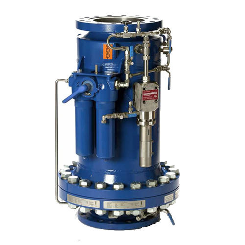
Building length, connections and materials can be customised to any requirement. The straightway valve with optimised design features the least possible flow loss. The valve cone is of the soft seal type.
- SR 6.2K is directly acting with piston actuation. The response pressure has been pre-set.
- SR 6.2P is pilot-controlled, the response pressure and the closing time are adjustable. If a second pilot valve is used, the valve can be switched to another pre-set response pressure.
The surge anticipation valve SAV 820E is designed for installation in a bypass line, prevents harmful pressure surges that can develop in pumping systems during sudden pump stoppage.
Unlike conventional pressure relief valves that open only when a high-pressure surge is encountered, the SAV820E already senses the preliminary stage of the high-pressure surge (pump failure or low-pressure surge) and opens in anticipation of the subsequently returning high-pressure surge. By pre-opening, the SAV820E inhibits the pressure rise before it occurs.
The SAV820E is a self-acting valve with two adjustable response pressures and adjustable closing behaviour. It consists of the main valve with two adjustable pilot valves and a throttle valve. It operates without auxiliary or external energy.
When the upper or lower response pressure is reached, the valve opens. At a pressure between the response pressures, the valve remains closed.
General Features & Benefits
- Compact design, lower weight and minimum space required compared to others.
- Optimal control behaviour through expertly designed throttles.
- Flow optimised constructions to allow high flows at lower differential pressures.
- High corrosion protection due to construction materials and coatings.
- High seat tightness/excellent leakage rates.
Customisable Special Options
- Coating as per DIN EN ISO 12944 C5-M, DIN 55633.
- Special materials such as Duplex, Super Duplex, Hastelloy, Titanium etc.
- Various materials for o-rings and seals such as FKM, EPDM, FFKM, Metallic, PTFE etc.
- Version for various installation positions.
- Customised special versions on request, such as straight-way valves, control by solenoid valve, diaphragm-operated, dome-loaded etc.
How to Select Surge Valves
In order for your anti surge valves function properly, they must be designed to fit your specific to your application. The specifics of your operating conditions (pressures, flows, temperatures, media, environmental conditions, line sizes etc.) will impact the individually designed solution. Things such as how many valves and pumps are in operation could affect the solution.
As a general 'rule of thumb', our surge valves are operating at approx. 25% of the maximum pipeline flow. Special attention must be paid to the flow rate (Kvs value) and the response pressures needed.
Oversizing with an excessively large Kvs value or an incorrectly selected lower set pressure can relieve too much operating media to the atmosphere in the event of a pressure surge, therefore making plant pressure recovery impossible.
The valve typically remains open until there is no longer any pressure differential across the valve. This loss of operating media will persist until the pipeline has run dry, or the liquid column will break off and subsequently cause high pressure rises when the liquid columns collide again ("macro cavitation").
Before designing the valves, we always recommend that a comprehensive surge analysis be carried out by a qualified engineering service provider. If required, we will discuss the analysis with you and the service provider and will be happy to advise on the correct selection of the valve.
A typical checklist summary of the factors to consider include:
- Flow rate (Kvs value) and set points (response pressure) that the valve should have.
- Flow rate and pressure during normal operation of the system.
- Static pressure of the system.
- Nominal diameters and preferred connection types.
- Material selection such as stainless steel or duplex steel. Elastomers for O-rings and seals are suitably designed for the requirements of the media and the operating temperature.
- Valve seat leakage classes such as III or V, optionally IV, according to DIN EN 60534-4 and/or ANSI FCI 70-2 (noting SRV and SAV are no shut-off devices which guarantee a tight valve closure).
Application Examples
Constant Pressure Control in Gas Treatment Plants
Natural gas is composed nearly entirely of highly combustible methane, but during extraction from the wellhead it contains various impurities, for example ethane, propane, butane, hydrogen, hydrogen sulphides, helium and others, which must be separated and removed prior to further processing.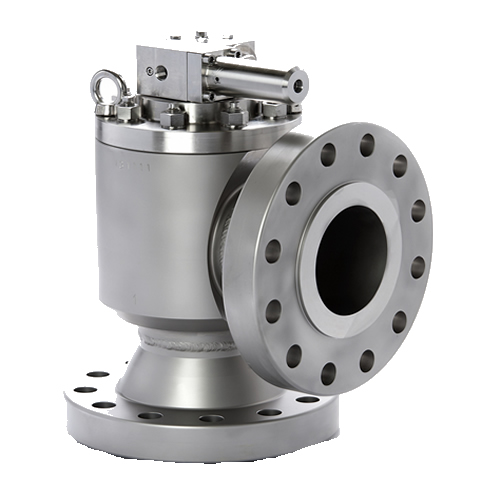
In a natural gas separation plant the incoming gas firstly flows through a filter ("slug catcher"), in which for example sand and other solid particles, water and/or crude oil are removed. Having a pressure of 34 - 40 bar, the gas is then conducted to a high pressure separator unit that is to separate all of the condensates from the gas.
Since the separator works at a pressure of 30 bar, the Mankenberg pressure control valve RP 810 ECK has been installed upstream of the unit. The valve constantly reduces the gas pressure to the required pressure of 30 bar. The flow rate varies between 1,890 and 26,295 Nm³/h at temperatures between 25 °C and 45 °C.
The pilot-operated pressure control valve RP810ECK consists of a main valve with a pilot valve, a throttle unit with integrated strainer, non-return valve and throttle valves which are permanently attached on the cover. The material is particularly corrosion-resistant in accordance with NACE. The medium-wetted parts (springs and mesh of the integrated strainer) are made of Inconel, the adjusting spring was produced from Duplex steel. The valve has a special hydraulic damping for gas applications, thus adapting in an optimal way the regulating behaviour to the plant.
Pipeline Protection in an Oil Camp
In an oil camp the crude is pumped through miles of oil pipelines. Natural hazards or technical problems may require the pump station to be shut down so that the fluid column in motion is stopped abruptly and generates a pressure surge. If the surge cannot escape from the system, there is reason to fear serious damage to the pipelines and the plant.
A leading oil and gas company in the Sultanate of Oman produces around 70,000 barrels of crude oil in the south of the country, which are then pumped to the north. The company protects the electronically controlled emergency shutdown system of its pump station by means of a Mankenberg surge relief valve SR 6.2.
Two pressure transmitters arranged at both sides of the pipeline are linked to the two pilot valves of the SR 6.2 by sense lines. In the event of a pressure surge arising after an emergency shutdown, the pilot valves open the surge relief valve that discharges the pressure surge out of the system into a pit. The identical pilot valves comply with severe safety standards.
Every individual valve can generate sufficient stroke motion to activate the SR 6.2. The surge relief valve has been specifically designed for this station and is completely made of stainless steel in accordance with NACE (MR0175).
Other Self-Acting Valve Solutions
Variety of our valves for pipeline and storage tank applications include:
Spring-Operated Pressure Control Valves |
Float-Operated Level Control Valves |
|
Why Use Mankenberg Valves?
As a leading manufacturer of self-acting control valves, Mankenberg is a specialist for stainless steel and special materials in deep-drawing processes. The key focus points at the heart of Mankenberg valves include: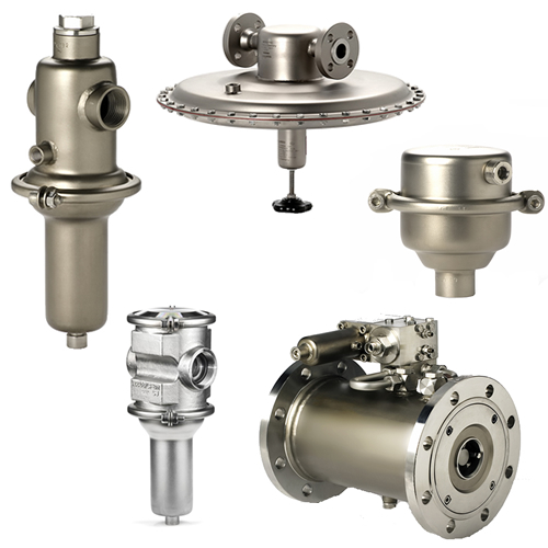
- Safety - continued mechanical option thanks to the self-acting design (no additional power needed).
- Costs - low cost of ownership with long operational life span, assembly and maintenance is minimal.
- Assembly and Operation - easy installation, low weight and compact designs.
- Sustainability - no cost of electricity to run and recyclability of any used materials.
For a more detailed breakdown on these features and benefits, check out our self-regulating pressure control valve guide here.
To get an overview on our solutions for pipelines and storage tanks, click here to download our free guide.
Still need some guidance? Contact our experienced technical team here for application support and advice on components for your system.